

How to Test an Inductor: Complete Guide with Multimeter, LCR Meter and Failure Diagnosis
Apr 09, 2026
Leave a message
Inductors are essential passive components widely used in power supplies, DC-DC converters, automotive electronics, RF circuits, and industrial equipment. When an inductor fails, it may cause unstable voltage, excessive heat, increased noise, or complete circuit failure.
So, how do you test an inductor and determine whether it is working properly?
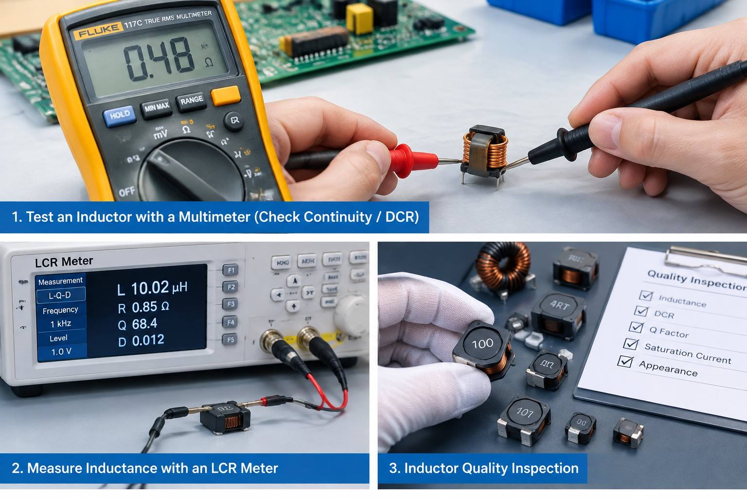
The testing method depends on the level of accuracy required. A digital multimeter can help identify basic problems such as open circuits and abnormal resistance, while an LCR meter can accurately measure inductance, DCR, impedance, and Q factor.
This guide explains how to test an inductor with a multimeter, LCR meter, and other inspection methods, helping engineers quickly identify defective components and improve circuit reliability.
Common Signs of a Bad Inductor
Before testing an inductor, it is important to understand common failure symptoms.
A damaged inductor may show:
- Unstable output voltage
- Excessive temperature rise
- Burning smell or visible damage
- Cracked magnetic core
- Broken winding
- Increased DC resistance (DCR)
- Incorrect inductance value
- Reduced circuit efficiency
Common causes of inductor failure include:
- Excessive current
- Magnetic core saturation
- Overheating
- Mechanical damage
- Shorted winding turns
- Manufacturing defects
For engineers, proper testing is necessary to confirm whether an inductor meets electrical specifications.
How to Test an Inductor: Basic Methods
A complete inductor test usually includes:
1.Visual inspection
2.Resistance measurement
3.Inductance measurement
4.Performance verification under operating conditions
Different testing methods provide different information about the condition of an inductor.
1. Visual Inspection of an Inductor
Visual inspection is the first step when checking an inductor.
Check the Winding
Inspect the winding for:
- Broken wires
- Burn marks
- Damaged insulation
- Loose winding structure
A broken winding usually causes an open circuit, preventing current flow.
Check the Magnetic Core
For ferrite core and power inductors, check for:
- Cracks
- Chipping
- Physical deformation
- Signs of overheating
A damaged core can change the magnetic properties and reduce inductance stability.
Check the Terminals
Inspect terminals or solder joints for:
- Oxidation
- Poor connections
- Broken leads
- PCB mounting problems
Poor connections may result in incorrect measurements.
2. How to Test an Inductor with a Multimeter
A digital multimeter (DMM) is the most common tool for basic inductor testing.
However, most standard multimeters cannot measure inductance directly. They can only test:
- Continuity
- DC resistance (DCR)
To measure actual inductance, an LCR meter is required.
Step-by-Step Multimeter Testing
Step 1: Disconnect the Inductor from the Circuit
Remove the inductor from the PCB or disconnect one terminal.
Testing an inductor while it is connected to other circuit components may produce inaccurate results.
Step 2: Set the Multimeter to Resistance Mode
Select the Ω (ohm) function on the multimeter.
Step 3: Measure Resistance Across the Terminals
Place the probes on both terminals of the inductor.
The measured resistance should usually be low because the winding is made from conductive wire.
How to Interpret Multimeter Results
| Reading | Possible Condition |
|---|---|
| Low resistance value | Winding is likely continuous |
| OL / Infinite resistance | Open winding or broken wire |
| Extremely low resistance | Possible short circuit |
| Abnormal resistance | Possible component damage |
The correct resistance value depends on the inductor design, wire size, inductance rating, and current capability.
3. How to Measure Inductance Using an LCR Meter
An LCR meter is the professional tool used to accurately test inductors.
It can measure:
- Inductance (L)
- Resistance (R)
- Impedance (Z)
- Quality factor (Q)
- Dissipation factor (D)
For engineering validation and production inspection, an LCR meter provides much more detailed information than a multimeter.
Steps to Test an Inductor with an LCR Meter
Step 1: Select the Correct Test Frequency
Different inductors require different measurement conditions.
For example:
- Power inductors are usually tested at lower frequencies
- RF inductors require higher-frequency testing
The test frequency should match the manufacturer's specifications whenever possible.
Step 2: Connect the Inductor to the LCR Meter
Connect the test leads securely to both terminals.
For small SMD inductors, dedicated fixtures or Kelvin probes can improve accuracy.
Step 3: Compare Results with the Datasheet
Check the measured values against specifications:
- Inductance value
- Inductance tolerance
- DCR
- Q factor
Large deviations may indicate:
- Core damage
- Shorted turns
- Overheating
- Incorrect component selection
4. Testing Inductor DCR (DC Resistance)
DC resistance is one of the most important parameters for power inductors.
Low DCR helps achieve:
- Lower power loss
- Higher efficiency
- Reduced heat generation
During manufacturing and quality inspection, DCR testing is commonly performed to ensure consistency.
Factors affecting DCR include:
- Copper wire diameter
- Winding structure
- Temperature
- Inductor size
An unexpected increase in DCR may indicate internal damage.
5. How to Check Inductor Saturation Problems
For power applications, current capability is a critical factor.
When an inductor exceeds its saturation current:
- Inductance decreases
- Ripple current increases
- Power losses rise
- Temperature increases
Typical symptoms include:
- Converter instability
- Excessive noise
- Overheating
- Reduced efficiency
Engineers should verify:
- Rated current
- Saturation current
- Temperature rise characteristics
6. Testing an Inductor on a Circuit Board
Sometimes engineers need to test an inductor without removing it from the PCB.
However, in-circuit testing has limitations because:
- Other components affect measurements
- Parallel circuits change resistance readings
- Circuit impedance influences results
For accurate testing, removing the component or isolating one terminal is recommended.
Common Inductor Failures and Test Results
| Failure Type | Test Result |
|---|---|
| Open winding | Infinite resistance |
| Shorted turns | Reduced inductance |
| Core damage | Unstable inductance |
| Overheating damage | Increased DCR |
| Saturation problem | Inductance drops under high current |
Multimeter vs LCR Meter for Inductor Testing
| Test Item | Multimeter | LCR Meter |
|---|---|---|
| Open circuit detection | ✓ | ✓ |
| Short circuit detection | ✓ | ✓ |
| DCR measurement | ✓ | ✓ |
| Inductance measurement | ✗ | ✓ |
| Q factor measurement | ✗ | ✓ |
| Frequency analysis | ✗ | ✓ |
For basic troubleshooting, a multimeter is usually enough.
For product development, quality control, and supplier inspection, an LCR meter is the recommended solution.
How Manufacturers Test Inductors During Quality Control
Professional inductor manufacturers use multiple inspection methods to ensure product reliability, including:
- Inductance testing
- DCR testing
- Q factor measurement
- Rated current testing
- Saturation current verification
- Temperature rise testing
- Appearance inspection
These tests help ensure inductors maintain stable performance in demanding applications.
How to Choose a Reliable Inductor Manufacturer
When selecting an inductor supplier, engineers should consider:
- Inductance accuracy
- Current handling capability
- Low DCR design
- Magnetic material quality
- Manufacturing consistency
- Custom design capability
- Testing and quality control processes
A reliable supplier should provide:
- Product datasheets
- Electrical test reports
- Application support
- Custom inductor solutions
Conclusion: The Right Way to Test an Inductor
Testing an inductor starts with visual inspection and resistance measurement, but accurate evaluation requires professional equipment such as an LCR meter.
A multimeter can quickly identify open circuits and abnormal resistance, while an LCR meter can verify inductance, DCR, Q factor, and other critical parameters.
Understanding how to test an inductor correctly helps engineers prevent failures, improve product reliability, and select the right components for their applications.
Need Reliable Inductors for Your Application?
Fullstar Electronics specializes in custom inductors, power inductors, SMD inductors, and magnetic components for industrial electronics, automotive systems, power supplies, and customized applications.
Our engineering team provides technical support, component selection assistance, and customized inductor solutions to meet different application requirements.
FAQ
1.Can I test an inductor with a multimeter?
Yes. A multimeter can check continuity and DC resistance to identify open or short circuits. However, it cannot accurately measure inductance.
2.What resistance should an inductor have?
The resistance depends on the inductor design, wire size, and rated current. Always compare the measured value with the manufacturer's specifications.
3.How do I know if an inductor is damaged?
Common signs include infinite resistance, abnormal heating, physical damage, reduced inductance, or unstable circuit performance.
4.What is the best tool to measure inductance?
An LCR meter is the standard instrument for measuring inductance, resistance, impedance, and Q factor.
5.Why does an inductor lose inductance?
Possible causes include magnetic saturation, shorted turns, core damage, overheating, or mechanical stress.
For more information, please contact us at sales@xfullstar.com