

How to Choose the Right Ferrite Core for Transformers and Inductors
Sep 15, 2025
Leave a message
Choosing the right ferrite core is essential for improving the efficiency, reliability, and performance of transformers, inductors, and power electronic devices. A suitable ferrite core can reduce power loss, control temperature rise, and ensure stable operation under high-frequency conditions.
However, with different ferrite materials, core shapes, sizes, and specifications available, selecting the correct ferrite core can be challenging.
This ferrite core selection guide explains the key factors you should consider when choosing a ferrite core for your application.
1. Understand Your Ferrite Core Application
The first step in selecting a ferrite core is to define its application.
Different magnetic components have different requirements:
| Application | Recommended Ferrite Core |
|---|---|
| Switching power supply transformer | MnZn ferrite core |
| High-frequency transformer | Low-loss MnZn ferrite core |
| EMI filter and noise suppression | NiZn ferrite core |
| Power inductor | Gapped ferrite core |
| DC-DC converter | High-performance ferrite core |
For example, ferrite cores used in SMPS transformers require low core loss and high magnetic efficiency, while ferrite cores for EMI suppression require high impedance at high frequencies.
Before choosing a core, confirm:
- Operating frequency
- Output power
- Working temperature
- Required inductance
- Installation space
These parameters determine the suitable ferrite material and core size.
2. Choose the Right Ferrite Core Material
Ferrite material selection is one of the most important steps in magnetic design.
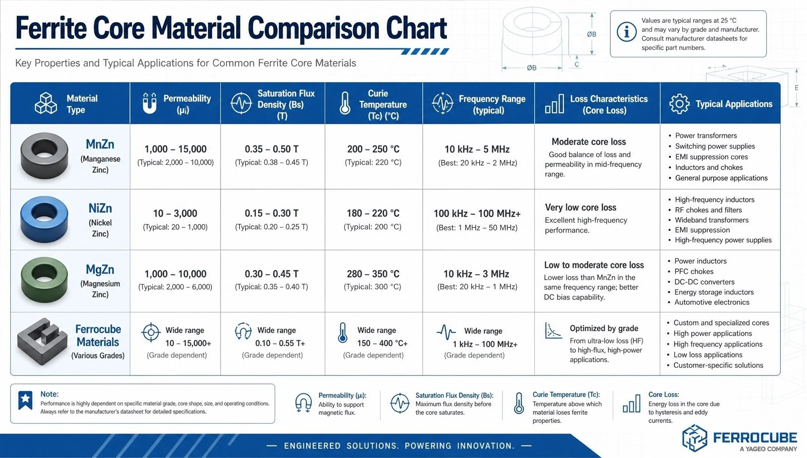
The two most common ferrite materials are MnZn ferrite and NiZn ferrite.
MnZn Ferrite Core
MnZn ferrite is widely used in power electronics because of its high permeability and low core loss at switching frequencies.
Typical applications:
- Power transformers
- SMPS transformers
- Inverters
- DC-DC converters
Advantages:
- Low power loss
- High magnetic permeability
- Excellent energy efficiency
NiZn Ferrite Core
NiZn ferrite is mainly used for high-frequency applications where electrical resistance and high-frequency performance are important.
Typical applications:
- EMI filters
- RF transformers
- Signal processing components
Advantages:
- Higher resistivity
- Better high-frequency characteristics
Choosing the correct ferrite material helps prevent overheating and improves the overall performance of magnetic components.
3. Select the Correct Ferrite Core Shape
Ferrite cores are available in different shapes, including EE, ETD, EER, PQ, RM, and toroidal cores.
Each shape has different advantages.
| Ferrite Core Shape | Main Applications |
|---|---|
| EE Core | General transformer applications |
| ETD Core | High-power switching transformers |
| EER Core | Power supplies and converters |
| PQ Core | Compact and high-efficiency power designs |
| RM Core | Space-limited and EMI-sensitive applications |
| Toroidal Core | Low leakage and filtering applications |
For example:
- EE and ETD cores provide large winding areas and are commonly used in power transformers.
- PQ and RM cores offer better magnetic shielding and compact designs.
- Toroidal cores provide low leakage magnetic fields.
The best core shape depends on your power level, PCB space, thermal requirements, and winding design.

4. Determine the Correct Ferrite Core Size
Choosing the correct ferrite core size is important for avoiding saturation and excessive temperature rise.
A ferrite core that is too small may cause:
- Magnetic saturation
- Increased power loss
- Overheating
- Reduced efficiency
A core that is too large may increase:
- Material cost
- Product size
- Weight
The main parameters to consider include:
- Effective core area (Ae)
- Window area (Aw)
- Magnetic path length (Le)
- AL value
- Maximum operating flux density
For transformer applications, core size is usually selected according to power rating and switching frequency.
For inductor applications, additional factors such as energy storage and DC bias current must be considered.
5. Consider Operating Frequency and Core Loss
Frequency has a major impact on ferrite core performance.
At higher frequencies, unsuitable materials may experience increased core loss and heat generation.
When selecting a ferrite core:
- Check the material loss curve
- Match the material with your operating frequency
- Consider temperature characteristics
For high-frequency switching applications, low-loss ferrite materials can significantly improve efficiency and reliability.
6. Common Mistakes When Selecting Ferrite Cores
Many design problems come from incorrect ferrite core selection.
Common mistakes include:
1. Selecting a core only by size
A physically larger core does not always provide better performance. Material characteristics and magnetic parameters are equally important.
2. Ignoring operating frequency
Using a ferrite material outside its recommended frequency range may increase losses.
3. Choosing the wrong core shape
Different applications require different geometries. A transformer core and an EMI filter core have different design requirements.
4. Not considering temperature rise
Ferrite magnetic properties change with temperature, so thermal performance must be evaluated.
7. How to Choose a Reliable Ferrite Core Manufacturer
- A reliable ferrite core supplier should provide:
- Stable material quality
- Accurate magnetic parameters
- Customized core solutions
- Strict quality control
- Engineering support
When working with a professional ferrite core manufacturer, engineers can receive support in:
- Material selection
- Core size recommendation
- Custom ferrite core design
- Sample testing
Fullstar provides high-quality ferrite cores for transformers, inductors, power supplies, and electronic applications. Our engineering team can help customers select the most suitable ferrite core based on frequency, power, and application requirements.
Conclusion
Choosing the right ferrite core requires considering multiple factors, including application, material, frequency, shape, size, and operating conditions.
The correct ferrite core selection can improve energy efficiency, reduce power loss, and increase product reliability.
If you need assistance selecting a suitable ferrite core for your transformer, inductor, or power electronics project, contact Fullstar for professional technical support.
Get expert advice on ferrite core selection today.
For more information, please contact us at sales@xfullstar.com