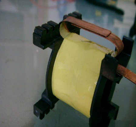
12V High-frequency Transformer Winding Diagram
Sep 19, 2018
Leave a message
High-frequency Transformer
The high-frequency transformer is a power transformer with a working frequency exceeding the intermediate frequency (10 kHz). It is mainly used as high-frequency switching power supplies in high-frequency switching power supply transformers, and also as high frequency inverter power transformer in in high-frequency inverter power supplies and high-frequency inverter welding machines. According to the working frequency, it can be divided into several grades: 10kHz - 50kHz, 50kHz - 100kHz, 100kHz ~ 500kHz, 500kHz ~ 1MHz, 10MHz or more.
Working Principle
A transformer is a device that converts alternating voltage, current, and impedance. When an alternating current is passed through the primary coil, an alternating magnetic flux is generated in the iron core (or core) to induce a voltage (or current) in the secondary coil.
The transformer consists of a core (or core) and a coil. The coil has two or more windings. The winding connected to the power supply is called the primary coil, and the other winding is called the secondary coil
Design Principle
In the design of high-frequency transformers, the leakage inductance and distributed capacitance of the transformer must be minimized because the high-frequency transformer in the switching power supply transmits a high-frequency pulse square wave signal. During transmission transients, leakage inductance and distributed capacitance can cause inrush currents and spikes, as well as top oscillations, resulting in increased losses. Usually, the leakage inductance of the transformer is controlled to be 1% to 3% of the primary inductance.
Leakage inductance of the primary coil—the leakage inductance of the transformer is caused by the fact that the magnetic flux between the primary and secondary coils is not fully coupled between the layers.
Distributed capacitance----the capacitance between the windings of the transformer, the upper and lower layers of the same winding, the different windings, the winding and the shielding layer is called the distributed capacitance.
The primary winding----the primary winding should be placed in the innermost layer, so that the length of the primary winding of the transformer can be minimized, so that the entire winding is minimized, which effectively reduces the distribution of the primary winding itself.
The secondary winding----After the primary winding, and the (3~5) layer of insulating pad is added to rewind. This reduces the capacitance of the distributed capacitance between the primary winding and the secondary winding, and also increases the dielectric strength between the primary and secondary, in accordance with the insulation withstand voltage requirements.
The bias winding—the bias winding is wound between the primary and secondary, or the outermost layer, and the switching power supply is adjusted based on the secondary voltage or the primary voltage.
12V High-frequency Transformer Winding Diagram
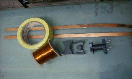
1.Preparation materials: PQ40, copper sheet 12MM*0.4MM 2 blocks, 0.53 lines * 2 winding, high temperature belt.
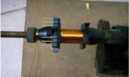
2.Secondary winding, firstly en-wind the 70T, then en-wind the rest.
3.Two pieces of copper skin en-wind in opposite directions.
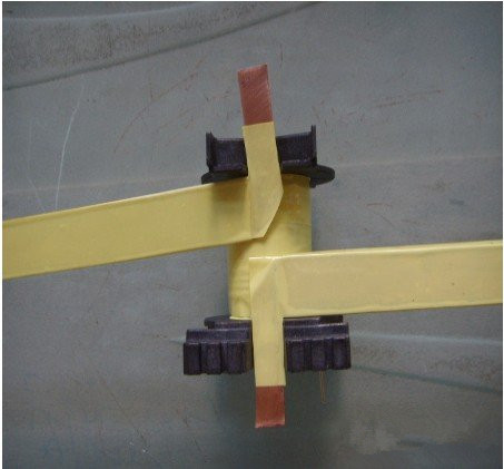
4.The copper sheet does not need to be cut short, and it is folded into a 90° angle.
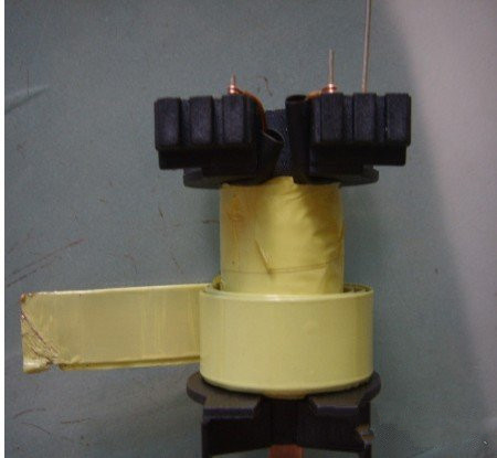
5.The primary winding is done.
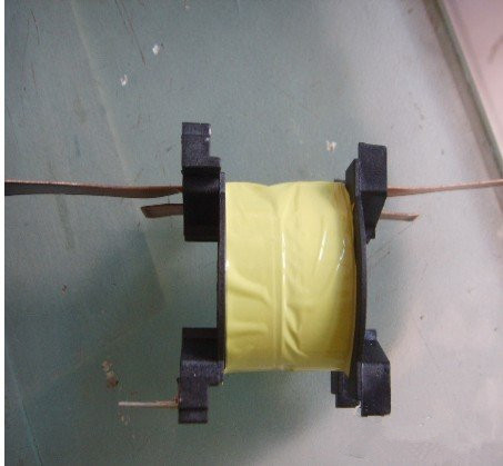
6.secondary winding en-wind the 70T and then en-wind again,in order to facilitate the voltage required. This will not occupy the space of the skeleton.
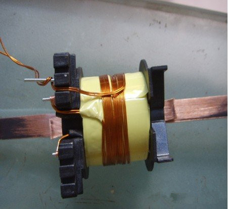
7.There is still a lot of space around the skeleton. If there is no copper, use the wire. Line up a strip of copper and stick it with double-sided tape.