

How to select inductors?
Sep 21, 2023
Leave a message
First, the basic principle of inductance
Inductors, along with capacitors and resistors, are three basic passive devices in electronics. The function of inductors is to store electrical energy in the form of magnetic field energy.
Taking cylindrical coil as an example, the basic principle of inductance is briefly introduced.

As shown in the figure above, when a constant current flows through the coil, a static magnetic field is formed in the indicated direction according to the right-hand helix rule. The inductor flows through the alternating current, the generated magnetic field is the alternating magnetic field, the changing magnetic field generates an electric field, and the induction electromotive force on the coil generates the induced current:
· When the current increases, the magnetic field becomes stronger, and the direction of the magnetic field changes is the same as that of the original magnetic field. According to the left-hand spiral rule, the induced current generated is in the opposite direction of the original current, and the inductance current decreases;
· When the current changes, the magnetic field becomes weaker, and the direction of the magnetic field changes is opposite to the direction of the original magnetic field. According to the left-hand spiral rule, the induced current generated is in the same direction as the original current, and the inductor current becomes larger.
This is Lenz's law, and the end effect is that the inductor will prevent the current flowing through it from changing, that is, the inductor has a high resistance to the alternating current. For the same inductance, the higher the current change rate, the greater the induced current, and the higher the impedance of the inductance; If the same current change rate, different inductors, if the induced current generated is greater, then the inductor presents a higher impedance.

It can be seen that the size of the inductance is related to the size of the coil and the material of the inner core.
The characteristics of actual inductance are not only the role of inductance, but also other factors, such as:
· The wire wound into the coil is not an ideal conductor, and there is a certain resistance;
· The magnetic core of inductance has a certain heat loss;
· There is a distributed capacitance between the conductors inside the inductor.
Therefore, it is necessary to use a more complex model to represent the actual inductance, and the commonly used equivalent model is as follows:

The equivalent model form may be different, but it should be able to reflect the loss and distributed capacitance. According to the equivalent model, two important parameters of the actual inductance can be defined.
Self-Resonance Frequency
Due to the existence of Cp, a resonant circuit is formed together with L, whose resonant frequency is the self-resonant frequency of the inductor. Before the self-resonant frequency, the impedance of the inductor increases with the increase of frequency. After the self-resonant frequency, the impedance of the inductor decreases as the frequency increases, and the capacitance is presented.
Quality Factor
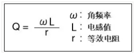
That is, the Q value of the inductor, the ratio of the inductive stored power to the loss power, the higher the Q value, the lower the loss of the inductor, and the direct current impedance of the inductor is directly related to the parameter. Self-resonant frequency and Q value are the key parameters of high frequency inductors
Second, the process structure of inductance
The process of inductance can be roughly divided into 3 kinds:
2.1 Wire Wound Type (Wire Wound Type)
As the name suggests, the copper wire is wound around a magnetic core to form a coil, and there are two ways to wind the wire:
Round Wound
Cylindrical winding is common and has a wide range of applications, such as:
Flat Wound
The advantage of planar winding is obvious, that is, the height of the device is reduced. It can be seen from the previous formula that the greater the permeability of the magnetic core, the greater the inductance value, and the magnetic core can be
· Non-magnetic materials: such as air core, ceramic core, it seems that it can not be called magnetic core; This inductance value is small, but there is basically no saturation current
· Ferromagnetic materials: such as ferrite, Permo alloy, etc.; The permeability of the alloy is higher than that of ferrite. Ferromagnetic material has magnetic saturation phenomenon and saturation current.
Winding inductance can provide high current and high inductance. The larger the magnetic core permeability, the same sensing value, less winding, less winding can reduce the DC resistance; The same size, less winding can be wound thick, improve the current.
In addition, in the power supply design, often encounter the problem of inductance howling, the essence is that the change of the magnetic field causes the conductor, that is, the vibration of the coil, the frequency of the vibration is just in the audio range, the human ear can hear, the alloy integrated forming inductance, more firm, can reduce vibration.
2.2 Multilayer Inductor (Multilayer Type)
The production process of multilayer chip inductors: the ferrite or ceramic paste is dried and formed, the conductive paste is alternately printed, and the integrated structure is formed by lamination and sintering.

The multilayer chip inductor is smaller than the winding inductor and has standardized package, which is suitable for automatic high density mounting. Integrated structure, high reliability, good heat resistance.
2.3 Thin Film Inductance (Thin Film Type)
Thin film inductors use a process similar to IC production, a layer of conductor film is plated on the substrate, and then the coil is formed by photolithography process, and finally the medium layer, insulation layer and electrode layer are added to package and form.
The production process of the thin film device is shown in the figure below


The precision of the lithography process is high, resulting in narrower lines and sharper edges. Therefore, thin film inductors have
· Smaller size, 008004 package
· Smaller Value Step, 0.1nH
· Smaller tolerance, 0.05nH
· Better frequency stability
Third, the application and selection of inductors
In circuit design, inductors have three main categories of applications:
· Power inductance: mainly used for voltage conversion, commonly used DCDC circuit to use power inductance;
Decoupling inductance: mainly used to filter out the noise on the power line or signal line, EMC engineers should be familiar with;
· High-frequency inductors: mainly used in RF circuits to achieve bias, matching, filtering and other circuits.
3.1 Power Inductance
Power inductors are commonly used in DCDC circuits to maintain a continuous current by accumulating and releasing energy.
Most power inductors are winding inductors, which can improve high current and high inductance.

Multilayer chip power inductors are also more and more, usually the inductance value and current are low, the advantage is that the cost is low, the volume is ultra-small, and there are more applications in products with large space restrictions such as mobile phones.

3.2 Decoupling inductors
The decoupling inductor is also called Choke, which is usually translated as choke coil in textbooks. The role of decoupling inductors is to filter out interference on the line, which belongs to EMC devices, EMC engineers are mainly used to solve the testing problems of radiation emission (RE) and conducted emission (CE) of products.
Decoupling inductors, usually relatively simple structure, mostly copper wire directly wound on the ferrite ring.
Differential mode inductance
Differential mode inductors are ordinary winding inductors, which are used to filter out some differential mode interference, mainly to form LC filters with capacitors to reduce power supply noise.

For 220V mains, differential mode interference is the interference between L phase and N phase. For POE, it is the interference between POE+ and POE-; For the low-voltage DC power supply on the mainboard, it is actually the power supply noise.
Differential mode inductor selection needs to pay attention to the following points:
• DC resistance, rated voltage and current, to meet the working requirements;
• Structure size to meet product requirements;
• Determine the noise frequency band through testing, and select the inductor according to the impedance curve of the inductor;
• Design LC filter, can do simple calculation and simulation.
Common mode inductors
The common mode inductor is to wind two coils with the same number of turns and opposite directions on the same ferrite ring.

Common mode inductors as shown above:
· When a common-mode component flows through the common-mode inductor, a magnetic field in the same direction will be formed in the two coils according to the right-handed rule, which is equivalent to a high inductance to the common-mode signal;
· When a differential mode component flows through a common mode inductor, according to the right hand rule, magnetic fields in opposite directions will be formed in the two coils and cancel each other, which is equivalent to a low inductive reactance to the differential mode signal.
Another way to understand: when V+ flows through a frequency of common mode interference, the formed alternating magnetic field will form an induced current on the other coil, according to the left hand rule, the direction of the induced current is opposite to the direction of the common mode interference on V-, which cancellations a part of the common mode interference.
Common mode inductors are mainly used in dual-wire or differential systems, such as 220V mains, CAN bus, USB signal, HDMI signal and so on. It is used to filter out common-mode interference, while the useful differential signal attenuation is small.
Common mode inductor selection needs to pay attention to the following points:
· The DC impedance should be low and cannot have a large impact on voltage or useful signals;
· For power lines, rated voltage and current should be considered to meet working requirements;
· The frequency band of common-mode interference is determined by testing, and the common-mode impedance should be high in this frequency band;
· The differential mode impedance should be small, which can not have a great impact on the quality of the differential signal;
Consider package size, do compatibility design. For example, common mode inductors for USB signals can be selected to be compatible with two 0402 resistors, and when common mode inductors are not required, 0402 resistors can be directly welded to reduce costs.
For more information, please contact us at sales@xfullstar.com